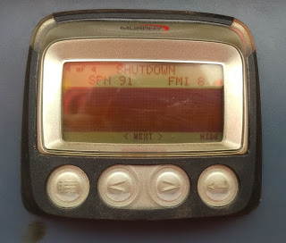
2020年8月30日星期日

How to Adjust Odometer on Hyundai i25 with OBDSTAR X300M?


OBDSTAR X300M is another new odometer adjustment tool launched by OBDSTAR. It’s designed completely according to industrial standard.It’s easy to take away and shockproofed.

OBDSTAR X300M Mileage Programmer Vehicle Coverage:
AUDI/VW/SKODA/SEAT, BENTLEY, BENZ, BESTURN, CHRYSLER(CHRYSLER/DODGE/JEEP), CITROEN, FORD, FIAT, GEELY, GM(BUICK/CADILLAC/CHEVROLET/HUMMER), GMC, GREATWALL, HYUNDAI, INFINITI, JAGUAR, KIA, LANDROVER, MAZDA, MITSUBISHI, NISSAN, OPEL, PEUGEOT, PORSCHE, PONTIAC, PROTON, RENAULT, ROEWE, SATURN, SMART, SSANGYONG, VOLVO etc.


Procedure:

OBDSTAR X300M HYUNDAI Odometer Car List:

Accent

D70F3536

2018

24C16

Azera

D70F3423

Creta

D70F3536

Elantra

D70F3536

Genesis

2015

D70F3536

Gets

24C16

HB20

D70F3423

I20

24C16

D70F3421

I20 Elite

I25

24C16

Sonata 9

D70F3536

Tucson

2016 D70F3536

Verna

24C16

Veloster

24C16

X-431 Actual Measurement 2013 Ford Focus Replaced Airbag Module Programming Method


X-431 Actual Measurement 2013 Ford Focus Replaced Airbag Module Programming Method

Vehicle Coverage: Ford Focus
Function Description: This function is used when you need to replace a new module (replace ECU) or initialize a module.

Test prerequisites and warnings:
The car is equipped with the programmable module and the module is communicating properly. The ignition switch is on. All cables and connectors are correctly connected. Communication fault may occur on the vehicle if the status is not good or the battery is low.

Procedure:
1.Choose Ford V46.20 or a later version.
2.Choose Automatic Search.
3.Choose System Selection.
4.Choose RCM (Airbag System).
5.Choose Special Function.
6.Choose Programming Module Installation. Read the hint carefully, check that conditions are met, and then click OK to perform the function.

7.Before installing the module, clear the DTCs first and configure an auxiliary power supply to keep the decoder power supply connected.

8.Turn the ignition key to ON (position II) and then click OK. The program starts reading old module information.

9.After reading, turn the ignition key to OFF (position I) and then click OK.

10.After the program completes reading old module information, install a new module. See Figure 5. Ensure that all cables and connectors are correctly connected and the decoder power supply is kept connected. After installation, click OK. The program starts writing new programmable module information.

11.Turn the ignition key to ON (position II) and then click OK.

12.Wait for the program running.

13.After program running is complete, turn the ignition key to OFF (position I) and click OK.

14.Turn the ignition key to ON (position II) and then click OK.

15.Wait the program to run for 10s.

16.Turn the ignition key to OFF (position I) and then click OK.

17.After the module is successfully installed, a program running success message is displayed. The new module information has been written. The function is complete and exits.

18.After program running is complete, stop and restart the engine to check whether the instrument cluster MIL is on and whether the replaced or initialized module can operate properly.

2020年8月11日星期二

Speed Control on Caterpillar Engines

Desired Speed Control

Speed-Control-on-Caterpillar-Engines-1

Top Engine Limit (TEL)
“TEL” is a customer programmable parameter that defines the maximum allowable engine speed for maximum power (Software Dependent). “TEL” can be programmed up to the maximum rated engine speed. “TEL” is defined along the engine’s lug curve.

Speed-Control-on-Caterpillar-Engines-2

Low Idle Speed
“Low Idle Speed” is the minimum allowable operating speed for the engine. This parameter can be programmed between 600 and 1400 rpm

High Idle Speed
“High Idle Speed” is the maximum no-load engine speed when the throttle or the PTO switch is in the maximum position (Software Dependent). “High Idle Speed” cannot be programmed lower than “TEL”. Read More: Setting LOW IDLE Speed and HIGH IDLE Speed on Caterpillar ET Software

Engine Acceleration Rate

“Engine Acceleration Rate” determines the rate of change of the engine speed (50 to 1000 rpm/s). This parameter may also help reduce smoke when you start the engine.

Intermediate Engine Speed
“Intermediate Engine Speed” defines the speed for the engine when the intermediate engine speed switch is activated. This parameter can be programmed to any engine speed between “Low Idle Speed” and “TEL”. Engine speed will increase or engine speed will decrease at the rate that is defined by the programmed value for “Engine Acceleration Rate”.

Desired Speed Input Configuration

Speed-Control-on-Caterpillar-Engines-3

Program the “Desired Speed Input Configuration” to match the type of input signal for desired engine speed. The desired speed input defines the type of signal that is used for the throttle control. A numeric value is used by Cat ET to set the input for the ECM. The following inputs are available:

0-5 VDC Input
4-20 mA Input
CAN Input – if the throttle signal is transmitted over the CAN J1939 data link.
PWM – if a throttle position sensor or direct fuel control is used (as Figure 1.1 above).

Throttle Input Low Idle Duty Cycle Setpoint
This parameter can be used to set the duty cycle for low idle. If the throttle position sensor that is used will not reach 10 % duty cycle, the duty cycle can be increased up to a maximum of 40 %.

Throttle Input High Idle Duty Cycle Setpoint
This parameter can be used to set the duty cycle for high idle. If the throttle position sensor that is used will not reach 90 % duty cycle, the duty cycle can be decreased to a minimum of 50 %.

Throttle Position Sensor
Program the “Throttle Position Sensor” to “Installed” if a throttle position sensor is used for desired speed control. Otherwise program this parameter to “Not Installed”.

Speed-Control-on-Caterpillar-Engines-4

PTO Mode

Speed-Control-on-Caterpillar-Engines-5

“PTO Mode” allows the ECM to be programmed to either one of the two PTO configurations that are available.

Ramp Up/Ramp Down – when “PTO Mode” is programmed to “Ramp Up/Ramp Down”, the ECM allows PTO operation with traditional features.
Set/Resume – when “PTO Mode” is programmed to “Set/Resume”, the ECM allows PTO operation with enhanced features.

Speed-Control-on-Caterpillar-Engines-6

#Additional Information:
-PTO Enable Switch – J1/P1:56
-PTO Rump Up/Set Switch – J1/P1:58
-PTO Rump Down/Resume Switch – J1/P1:60
-Intermediate Engine Speed Switch – J1/P1:45
-Throttle Position 1 (PWM) – J1/P1:66
-Throttle Position 2 (PWM) – J1/P1:68

Throttle Position Signal Abnormal (Error Code SPN 91 – FMI 8)

 SPN91 FMI8

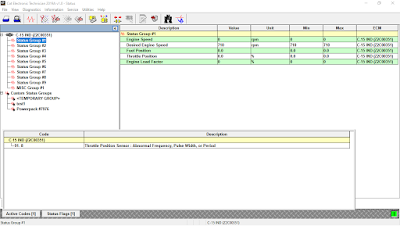
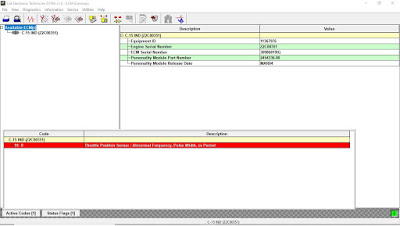
CID 0091 FMI 08 Throttle Position Signal Abnormal

Throttle-Position-Signal-Abnormal-Error-Code-SPN-91-FMI-8-1

MID 036 CID 0091 FMI 08

Conditions Which Generate This Code:
The Electronic Control Module (ECM) detects an incorrect frequency on the throttle signal.

System Response:
The code is logged. The ECM flags the throttle position as invalid data and a default value of zero percent is used.

Possible Performance Effect:
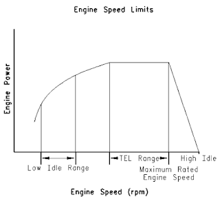
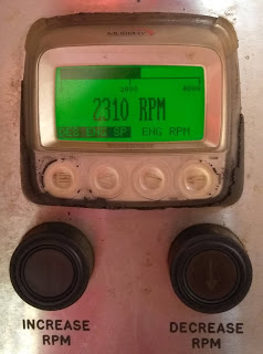
The engine speed is limited to low idle.

Throttle-Position-Signal-Abnormal-Error-Code-SPN-91-FMI-8-2

Troubleshooting:
Throttle Position Sensor Circuit – Test

System Operation Description:
Use this procedure to troubleshoot any suspect problems with the throttle position sensor. Also use this procedure to troubleshoot an active 91-08 Throttle Signal Abnormal.

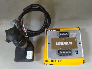
The throttle position sensor eliminates the mechanical throttle and governor linkages. The sensor that is installed depends on the engine’s configuration.
Figure 1.2 – Throttle Position Sensor (with a knob and electronic)
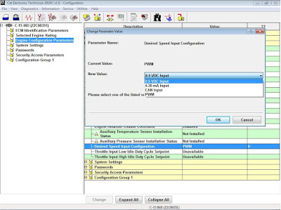
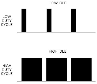
Refer to Figure 1.3 – The sensor creates a signal that is Pulse Width Modulated (PWM). The duty cycle varies with the throttle position. The signal has a low duty cycle when the throttle is at low idle (0-22%). The signal has a high duty cycle when the throttle is at high idle (75-100%). The Electronic Control Module (ECM) processes the signal in order to control the engine speed.

Throttle-Position-Signal-Abnormal-Error-Code-SPN-91-FMI-8-3

The signal from the throttle position sensor has a specific frequency. The frequency of the signal must be between 150 Hz and 1050 Hz or the ECM will activate a 091-08 diagnostic code.

Throttle-Position-Signal-Abnormal-Error-Code-SPN-91-FMI-8-4

Test Step 1. Inspect the Electrical Connectors and the Wiring
A. Turn the keyswitch to the OFF position.
B. Thoroughly inspect J1/P1 ECM connector and P61 Customer connector (if available). Inspect the connections on the throttle position sensor.
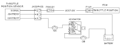
P1 terminal that is associated with the throttle position sensor:
(P1-66) Throttle position), J1/P1 ECM connector.
(10) Throttle position), J61 and P61 Customer connector.

C. Perform a 45 N (10 lb) pull test on each of the wires that are associated with the throttle position sensor.

D. Check the Allen head screw on each ECM connector and the customer connector for the proper torque.
Expected Result: All connectors, pins, and sockets are completely coupled and/or inserted, and the harness and wiring are free of corrosion, of abrasion, and of pinch points.
If Not OK: Repair the wiring and/or the connectors. Replace parts, if necessary. Ensure that all of the
seals are properly connected. Verify that the repair eliminates the problem.

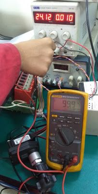
Test Step 2. Check for Supply Voltage at the Throttle Position Sensor
A. Monitoring Cat ET, check “Active Diagnostic” code (91-8) – Throttle Position Sensor: Abnormal Frequency, Pulse Width, or period. Read More: How to Connecting Caterpillar ET Software to the ECM

Throttle-Position-Signal-Abnormal-Error-Code-SPN-91-FMI-8-5

B. Disconnect the P403 connector (TPS connector).
C. Turn the keyswitch to the ON position. The engine should be off.
D. Measure the voltage between terminals P403-A and P403-B (Pin A – B)

Expected Result: The supply voltage is at least 11 VDC for a 12 volt system. The supply voltage is at least 22 VDC for a 24 volt system.
If Not OK: The configuration of the wiring between the +Battery and the throttle position sensor depends on the engine’s configuration. The problem could be in the wiring or in a connector. There may be a problem with the battery.Perform the necessary repairs. Verify that the problem is resolved.

Test Step 3. Check the Signal Wire for a Short Circuit
A. Turn the keyswitch to the OFF position.
B. Disconnect the P1 ECM connector.
Note: Be sure to wiggle the harnesses during the following measurements. Be sure to wiggle each
harness near each connector.
C. Measure the resistance between terminal P1-66 and all of the other terminals in the P1 ECM connector.
Expected Result: Each resistance measurement indicates an open circuit.
If Not OK: The problem could be in the wiring or in a connector. Repair the wiring and/or the connector, when possible. Replace parts, if necessary. Verify that the problem is resolved.
Throttle-Position-Signal-Abnormal-Error-Code-SPN-91-FMI-8-6
Test Step 4. Check the Signal Wire for an Open Circuit
Note: Be sure to wiggle the harnesses during the following measurement. Be sure to wiggle each harness near each connector.
-Measure the resistance between terminal P1-66 and terminal P403-C (Pin C – TPS Signal).
Expected Result: The resistance measurement is less than 10 ohms.
If Not OK: The problem could be in the wiring or in a connector. Repair the wiring and/or the connector, when possible. Replace parts, if necessary. Verify that the problem is resolved.

Test Step 5. Check the Frequency or Duty Cycle of the Throttle Position Signal at the ECM

A. Connect a multimeter between terminal P1-66 on and the engine ground stud.
B. Turn the keyswitch to the ON position.
C. Measure the frequency or duty cycle of the throttle position signal. Slowly move the throttle from low idle to high idle and back to low idle while you measure the frequency of the signal.
Expexted results:
-The frequency of the signal remains between 150 Hz and 1050 Hz as you move the throttle.
-Duty cycle is between 5% and 100% (0-5 Vdc).

Throttle-Position-Signal-Abnormal-Error-Code-SPN-91-FMI-8-7